Operator Library: Hardware Platform
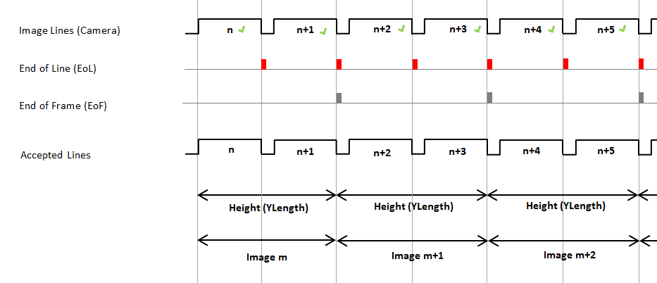
This operator generates the trigger (Exsync) for the camera. It is also responsible for assembling the acquired lines to images.
It is possible to use an internal signal generator (GrabberControlled) or to trigger the signal generator from external signals, either by input signals from the trigger expansion board (TTL Trigger board or OPTO Trigger board), or by software. The signal generator can produce Exsync signals with a flexible delay, pulse width and polarity. Additionally, a flash signal which is available at the trigger expansion board is generated.
The operator occupies 4 digital outputs and one camera port for the CC signals. Hence, one VisualApplets resource of type CameraControl is used. If the resource index is set to 0, the digital outputs 0 to 2 and camera port A is used. If the resource index is set to 1, the digital outputs 4 to 6 and camera port B is used. Outputs 3 and 7 are not used by the operator. Note that no other operators can use these hardware resources. Set the resource index in the resource dialog.
| Available for Hardware Platforms |
|---|
| microEnable IV VD1-CL/-PoCL |
| microEnable IV VD4-CL/-PoCL |
| Link Parameter | Input Link I | Output Link O |
|---|---|---|
| Bit Width | [1, 64] | as I |
| Arithmetic | {unsigned, signed} | as I |
| Parallelism | any | as I |
| Kernel Columns | 1 | as I |
| Kernel Rows | 1 | as I |
| Img Protocol | VALT_LINE1D | VALT_IMAGE2D |
| Color Format | any | as I |
| Color Flavor | any | as I |
| Max. Img Width | any | as I |
| Max. Img Height | 65536 | as I |
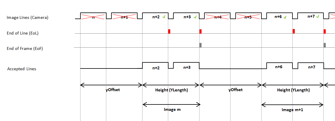
| YOffset | |
|---|---|
| タイプ | dynamic/static read/write parameter |
| Default | 0 |
| 範囲 | [0, 224] |
|
This parameter defines the number of lines omitted at the beginning of a frame. |
|
| YLength | |
|---|---|
| タイプ | dynamic/static read/write parameter |
| Default | 1024 |
| 範囲 | [8, 224] |
|
This parameter defines the number of lines of a frame. |
|
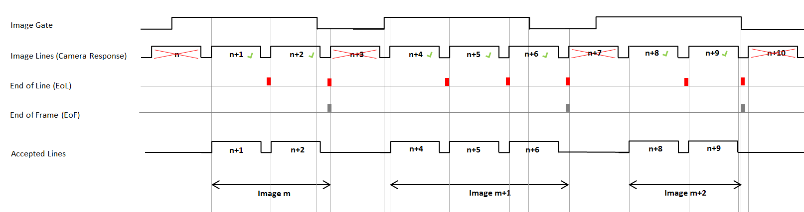
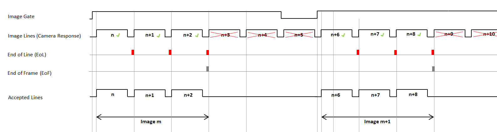
| MaxGatedHeight | ||||
|---|---|---|---|---|
| タイプ | dynamid read/write parameter | |||
| Default | restricted | |||
| 範囲 | {restricted, unrestricted} | |||
|
The parameter MaxGatedHeight allows you to limit the maximum image height when the image trigger mode (ImgTriggerMode) is set to ExternSw_Gate. If if the image trigger mode (ImgTriggerMode) is set to ExternSw_Gate, and the parameter MaxGatedHeight is set to unrestricted, the image height is defined by the time the gate is open, i.e., by the pulse width of the external image trigger signal or the duration of the software trigger being value 1. Now, if the gate is open for a long time, the image height gets large. If parameter MaxGatedHeight is set to restricted, the image height is limited to YLength image lines even if the gate is still open. The operator will discard any further lines and wait for the next open gate to start a new frame. In contrast, if the parameter is set to unrestricted, the image height is only defined by the gate.
|
||||
![[Warning]](../common/images/admon/warning.png)
| LineTriggerMode | |
|---|---|
| タイプ | dynamic/static read/write parameter |
| Default | GrabberControlled |
| 範囲 | {GrabberControlled, Extern_Trigger, GrabberControlled_Gated_by_Img, Extern_Trigger_Gated_by_Img} |
|
This parameter selects the operation mode for the internal Exsync signal generator. The source for the external trigger input can by selected via the parameters LineTrgInSourceA and LineTrgInSourceB (see below). GrabberControlled: Exsync is generated periodically by the internal signal generator Extern_Trigger: An external trigger signal is used to start the signal generator once GrabberControlled_Gated_by_Img: Exsync is generated periodically by the internal signal generator during the acquisition of a frame Extern_Trigger_Gated_by_Img: An external trigger signal is used to trigger the signal generator during the acquisition of a frame |
|
| ExsyncEnable | |
|---|---|
| タイプ | dynamic read/write parameter |
| Default | OFF |
| 範囲 | {OFF, ON} |
|
Enables or disables the Exsync output to the camera. |
|
| LineTrgInSourceA | |
|---|---|
| タイプ | dynamic/static read/write parameter |
| Default | InSignal0 |
| 範囲 | {InSignal0, InSignal1, InSignal2, InSignal3, InSignal4, InSignal5, InSignal6, InSignal7} |
|
This parameter specifies the signal source which is used to trigger the Exsync signal generator. This is only relevant if the TriggerMode is set to Extern_Trigger. |
|
| LineTrgInSourceB | |
|---|---|
| タイプ | dynamic/static read/write parameter |
| Default | InSignal0 |
| 範囲 | {InSignal0, InSignal1, InSignal2, InSignal3, InSignal4, InSignal5, InSignal6, InSignal7} |
|
This parameter specifies the signal source which is used to trigger the Exsync signal generator. This is only relevant if the TriggerMode is set to Extern_Trigger and EncoderABMode is set to Signal_AB_Filter. |
|
| EncoderABMode | |
|---|---|
| タイプ | dynamic/static read/write parameter |
| Default | Signal_A_Only |
| 範囲 | {Signal_A_Only, Signal_AB_Filter, Signal_ABx2_Filter, Signal_ABx4_Filter} |
|
This parameter specifies whether a single trigger input (A only) is used for the Exsync generation, or the signals A and B. 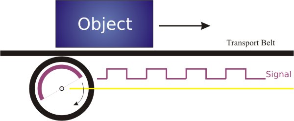 Signal A/B support enables to determine the revolving direction of the shaft encoder and to suppress and compensate backward movements: 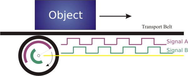
 Signal_A_Only: The trigger input selected by LineTrgInSourceA is used for Exsync generation. Signal_AB_Filter: Exsync is generated for a forward rotation of the shaft encoder in single resolution, i.e., a trigger pulse for a rising edge of LineTrgInSourceA. Signal_ABx2_Filter: Exsync is generated for a forward rotation of the shaft encoder in double resolution, i.e., a trigger pulse for a rising edge of LineTrgInSourceA and a falling edge of LineTrgInSourceA. Both edges of LineTrgInSourceA are used. Signal_ABx4_Filter: Exsync is generated for a forward rotation of the shaft encoder in quad resolution, i.e., a trigger pulse for a rising and a falling edge of LineTrgInSourceA and a rising and a falling edge of LineTrgInSourceB. Related Parameters when AB support enabled:
You can reset the shaft encoder by setting parameter EncoderABMode to value Signal_A_Only. |
|
| EncoderABLead | |
|---|---|
| タイプ | dynamic/static read/write parameter |
| Default | Signal_AB |
| 範囲 | {Signal_AB, Signal_BA} |
|
A foreward movement is defined by a rising edge of signal A before signal B if the parameter is set to Signal_AB, or vice versa: Signal_AB: Forward is defined by A before B Signal_BA: Forward is defined by B before A |
|
| LineTrgInPolarity | |
|---|---|
| タイプ | dynamic read/write parameter |
| Default | LowActive |
| 範囲 | {LowActive, HighActive} |
|
The parameter defines the polarity of the external input trigger signal LineTrgInSourceA and LineTrgInSourceB. When set to LowActive, the Exsync generator starts on a falling edge of the signal specified by the parameter ImgTrgInSource. Otherwise, the Exsync generation starts on a rising edge. This is only relevant if the TriggerMode is set to Extern_Trigger. |
|
| LineTrgDownscaler | |
|---|---|
| タイプ | dynamic/static read/write parameter |
| Default | 1 |
| 範囲 | [1, 256] |
|
This parameter specifies the number of external input trigger signals, which are needed to generate the Exsync. This is only relevant if the TriggerMode is set to an external trigger mode. |
|
| LineTrgPhase | |
|---|---|
| タイプ | dynamic/static read/write parameter |
| Default | 1 |
| 範囲 | [1, 256] |
|
This parameter specifies the number of external input trigger signals, which are needed to generate the first Exsync of a frame. This is only relevant if the TriggerMode is set to Extern_Trigger_Gated_by_Img. |
|
| ExsyncPeriod | |
|---|---|
| タイプ | dynamic/static read/write parameter |
| Default | 100 μs |
| 範囲 | [1.024, 4000] μs |
|
This parameter specifies the period of the Exsync signal. Therefore, it defines the line frequency when using the grabber controlled mode to trigger the connected camera. |
|
| ExsyncExposure | |
|---|---|
| タイプ | dynamic/static read/write parameter |
| Default | 20 μs |
| 範囲 | [1.024, 2000] μs, must not exceed ExsyncPeriod |
|
This parameter specifies the pulse width of the Exsync signal, which can be used by many cameras to specify the exposure time. Therefore, it is possible to adjust the exposure time via software, even while grabbing. |
|
| Exsync2Delay | |
|---|---|
| タイプ | dynamic/static read/write parameter |
| Default | 0 μs |
| 範囲 | [0, 2000] μs, must not exceed ExsyncPeriod |
|
This parameter specifies the delay of the generated Exsync signal, with respect to an external trigger input. Therefore, the Exsync2 signal is a delayed clone of the Exsync (polarity, period, etc. are the same as for Exsync). |
|
| ExsyncPolarity | |
|---|---|
| タイプ | dynamic/static read/write parameter |
| Default | LowActive |
| 範囲 | {LowActive, HighActive} |
|
The parameter adjusts the polarity of the Exsync signal genarator to the polarity accepted by the connected camera. Use LowActive, if the camera opens the shutter on a falling edge, otherwise use HighActive. |
|
| ImgTriggerMode | |
|---|---|
| タイプ | dynamic/static read/write parameter |
| Default | FreeRun |
| 範囲 | {FreeRun, ExternSw_Trigger, ExternSw_Gate} |
|
This parameter selects the operation mode for the internal Image Gate. The image trigger input signal may be created by external (peripheral) devices (e.g., shaft encoder), or by software. The source for the external image trigger input you can select via the parameter ImgTrgInSource, see below). The values of parameter ImgTriggerMode induce the following behaviour:
|
|
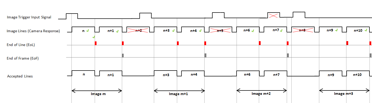
| ImgTrgInSource | |
|---|---|
| タイプ | dynamic/static read/write parameter |
| Default | InSignal0 |
| 範囲 | {InSignal0, InSignal1, InSignal2, InSignal3, InSignal4, InSignal5, InSignal6, InSignal7} |
|
This parameter specifies the signal source which is used to trigger the image acquisition. This is only relevant if the ImgTriggerMode is set to ExternSw_Trigger or ExternSw_Gate. |
|
| ImgTrgInPolarity | |
|---|---|
| タイプ | dynamic read/write parameter |
| Default | LowActive |
| 範囲 | {LowActive, HighActive} |
|
The parameter defines the polarity of the external input trigger signal. |
|
| ImgTrgDelay | |
|---|---|
| タイプ | dynamic read/write parameter |
| Default | 0 |
| 範囲 | {0, 4095} |
|
The parameter delays the image trigger signal by the given number of image lines. |
|
| FlashEnable | |
|---|---|
| タイプ | dynamic read/write parameter |
| Default | OFF |
| 範囲 | {OFF, ON} |
|
Enables or disables the flash output. The pulse width of the flash signal is equal to one line period. |
|
| FlashPolarity | |
|---|---|
| タイプ | dynamic/static read/write parameter |
| Default | LowActive |
| 範囲 | {LowActive, HighActive} |
|
The parameter defines the polarity for the generated Flash signal. |
|
| FlashDelay | |
|---|---|
| タイプ | dynamic/static read/write parameter |
| Default | 0 |
| 範囲 | {0, 4095} |
|
This parameter specifies the number of lines to delay the generated Flash signal, with respect to an external trigger input. Therefore, it is possible to synchronize the flash to the external trigger input. The pulse width of the flash signal is equal to one line period. |
|
| SoftwareTrgPulse | |
|---|---|
| タイプ | dynamic/static write parameter |
| Default | |
| 範囲 | {1} |
|
Setting this parameter to 1 will generate a software trigger. This is only relevant if the TriggerMode is set to an external trigger mode and ImgTrgInSource is set to SoftwareTrigger. |
|
| SoftwareTrgInput | |
|---|---|
| タイプ | dynamic/static write parameter |
| Default | |
| 範囲 | {0, 1} |
|
With this parameter a software gate can be produced for the image trigger mode ExternSw_Gate. |
|
| ImgTrgIsBusy | |
|---|---|
| タイプ | dynamic/static read parameter |
| Default | 0 |
| 範囲 | {0, 1} |
|
The ImgTrgIsBusy parameter enables software readout of the busy state for the image trigger. If busy then this parameter is set to 1 to reflect an ongoing image capture. If set to 0 then the operator is not busy. |
|
| CC1output | |
|---|---|
| タイプ | dynamic/static write parameter |
| Default | Exsync |
| 範囲 | {Exsync, ExsyncInvert, Hdsync, HdsyncInvert, Flash, FlashInvert, Gnd, Vcc} |
|
This parameter specifies the signal available at the CC1 line of the CameraLink cable. |
|
| CC2output | |
|---|---|
| タイプ | dynamic/static write parameter |
| Default | Exsync |
| 範囲 | {Exsync, ExsyncInvert, Hdsync, HdsyncInvert, Flash, FlashInvert, Gnd, Vcc} |
|
This parameter specifies the signal available at the CC2 line of the CameraLink cable. |
|
| CC3output | |
|---|---|
| タイプ | dynamic/static write parameter |
| Default | Exsync |
| 範囲 | {Exsync, ExsyncInvert, Hdsync, HdsyncInvert, Flash, FlashInvert, Gnd, Vcc} |
|
This parameter specifies the signal available at the CC3 line of the CameraLink cable. |
|
| CC4output | |
|---|---|
| タイプ | dynamic/static write parameter |
| Default | Exsync |
| 範囲 | {Exsync, ExsyncInvert, Hdsync, HdsyncInvert, Flash, FlashInvert, Gnd, Vcc} |
|
This parameter specifies the signal available at the CC4 line of the CameraLink cable. |
|
| ImgTrgDebouncingMaxTime | |
|---|---|
| タイプ | static write parameter |
| Default | 65.520 us |
| 範囲 | [0.016, 1000000] us |
|
This parameter specifies the maximal time for ImgTrgDebouncingTime parameter. The smaller the maximal time the less FPGA resources are required to implement the debouncing timer. |
|
| ImgTrgDebouncingTime | |
|---|---|
| タイプ | dynamic/static write parameter |
| Default | 0.112 us |
| 範囲 | [0.016, ImgTrgDebouncingMaxTime] us |
|
This parameter specifies the debouncing time the input image trigger signal must keep the same value to be detected as such. Fast signal changes within the debounce time will be filtered out. |
|
| LineTrgDebouncingMaxTime | |
|---|---|
| タイプ | static write parameter |
| Default | 65.520 us |
| 範囲 | [0.016, 1000000] us |
|
This parameter specifies the maximal time for LineTrgDebouncingTime parameter. The smaller the maximal time the less FPGA resources are required to implement the debouncing timer. |
|
| LineTrgDebouncingTime | |
|---|---|
| タイプ | dynamic/static write parameter |
| Default | 0.112 us |
| 範囲 | [0.016, ImgTrgDebouncingMaxTime] us |
|
This parameter specifies the debouncing time the input line trigger signals must keep the same value to be detected as such. Fast signal changes within the debounce time will be filtered out. |
|
The use of operator TrgPortLine is shown in the following examples:
-
'Allocation of Device Resources'
Learn the allocation of the device resources of the operator.
-
'Camera Link Line Scan Cameras '
Tutorial - Basic Acquisition
-
'Filter for Line Scan Cameras'
Examples - Explains how to implement a filter for line scan cameras.
